|
|
||||||
|
|
|
|
Download | |||
Diamond Version 5 User Manual: Display of structure pictureProjection
Previous article: Models Overview
This article will tell you how Diamond projects the structure from the Angstroem-sized real world into the structure picture.
· Diamond uses two kinds of projection: parallel and central projection ("perspective").
· The enlargement factor is used to transform the Angstroem 3D view coordinates into centimeter coordinates.
· The structure picture can be adjusted to fit in the structure window.
· The viewing distance is used for central projection and defines the perspective impression.
· "Distortion of Atoms and Bonds" gives some workarounds to avoid distortions of atoms in central projection.
· Both enlargement factor and viewing distance can be changed with the mouse or with the keyboard. · A rectangular area of the structure window can be zoomed. The last paragraph of this article tells you how to use stereo representation.
Parallel and Central Projection
To display the objects (atoms, bonds, etc.) of the structure on the two-dimensional area of the picture (screen or printout) the view coordinates of the objects
must be converted from the three-dimensional world with Angstroem units to a two-dimensional coordinate system with centimeter units.
There are two different methods to consider the z-coordinate, that means the depth, of the objects:
· Parallel projection simply ignores the z-coordinates of the objects and uses the enlargement factor only to convert the Angstroem units of the objects to centimeter units on the picture.
· Central projection regards the z-coordinates relative to the position of the viewer. This position is indirectly defined by both enlargement factor and viewing distance (in centimeters). Objects in the rear become smaller, whereas objects in the front become bigger than in parallel projection.
For both projection methods, the current center of rotation is an important reference point. This point will be placed into the center of the picture (screen or printout). But you can shift the projection of this reference point within the picture (see "Orientation and Position").
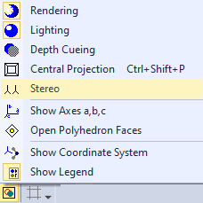
To change between parallel and central projection:
· Choose the Picture Settings command from the Display menu, which opens the Picture Settings dialog.
On the Projection page of this dialog, check the parallel radio button for parallel projection, or the central radio button for central projection;
· or: use the "hotkey" Shift+Ctrl+P;
· or: push the Picture Settings button
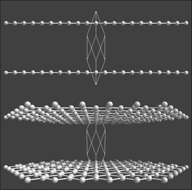
The following illustration compares two layers in graphite to show extreme perspective effects. The parallel projection in the upper and the central projection in the lower half (viewing distance: 25 centimeters, enlargement factor: 0.8 centimeters per Angstroem):
Enlargement Factor
The enlargement factor is used to transform the view coordinates of the objects from Angstroem units to the two-dimensional centimeter units of the picture (screen or printout).
In parallel projection, this value is used to transform the x- and y-coordinates of the objects, while the z-coordinate (the depth) is ignored.
If central projection is used instead, the enlargement factor refers to the z-position of the current center of rotation,
whereas objects nearer than the center are represented bigger, but those behind smaller. The perspective effect depends on the current viewing distance.
To edit the enlargement factor, choose the Picture Settings command from the Display menu, which opens the Picture Settings dialog.
On the Projection page of this dialog, edit the input field Enlargement factor. You can also change the enlargement factor incrementally using the keyboard or the mouse.
Adjusting the Structure
You can adjust the structure picture to the current size of the structure window or the size of the
bitmap or page, depending on the picture layout (see "Layout").
Adjusting can be done manually or automatically.
When Diamond adjusts the structure, it changes the enlargement factor and the
position of the projection of the structure within the drawing area (see "Orientation and Position")
until the picture fits into its frame, regarding a given border.
Adjusting the structure manually
To adjust the picture to the current size of its window (or bitmap or page), push the dropdown arrow right beneath
the
Defining the border for adjusting
You can define a border for the adjustment procedure. The default value is one centimeter for all four borders of the window or printout page, rsp.
To change the border, choose the Adjust command from the Display menu and change the values in the input fields of the Adjust dialog.
Automatic adjustment You can make Diamond adjust the structure whenever it needs redrawing, that means whenever the structure picture changes. For that, choose the Adjust command from the Display menu and check the checkbox Automatic adjustment in the Adjust dialog.
Viewing Distance
The viewing distance defines the distance between your viewing position (or the "camera" position) and the drawing area or the screen, rsp.
More exactly it is the distance between the current center of rotation of the structure and the viewers' position on the z-axis of the view coordinate system.
The distance is given in centimeters (cm). The perspective impression is the stronger the lower this distance is set.
Additionally a big enlargement factor contributes to this impression, because the distance is defined in cm and thus depends on the enlargement factor.
In extreme cases, i.e. if objects are positioned on a level with the viewer or even behind him, the drawing of these objects will be suppressed.
To edit the viewing distance, choose the Picture Settings command from the Display menu, which opens the Picture Settings dialog.
On the Projection page of this dialog, edit the input field Camera distance.
Assure that the central radio button is checked, since the viewing distance takes no effect in parallel projection. You can also change the viewing distance incrementally using the keyboard or the mouse.
Distortion of Atoms and Bonds
When using central projection, objects (especially atom spheres or ellipsoids) are distorted. That means, spheres become "eggs" in extreme cases (big enlargement factor and small viewing distance).
In flat representation,
Diamond does not regard this distortion for atom spheres, so that they will simply be projected as circles, whereas ellipsoids will be distorted correctly.
For that reason, the piercing points of bonds may not touch the atoms correctly.
To avoid this problem, either use rendered representation, or represent the spheres as ellipsoids, as far as displacement parameters have been defined.
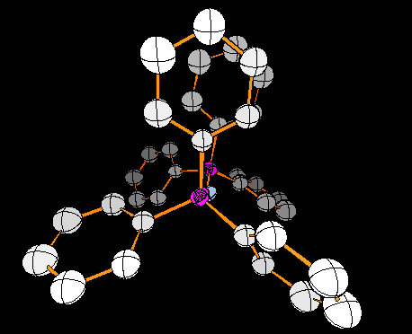
The following picture shows extreme distortions for a bis(triphenylphosphineiminium) molecule with an enlargement factor of 1 cm/Å and a viewing distance of 10 cm:
Changing Enlargement Factor or Viewing Distance With Mouse or Cursor
You can change both enlargement factor and viewing distance with the mouse or with the keyboard.
Using the mouse To change the enlargement factor or the camera distance or to walk through the structure picture, activate the tracking mode using the corresponding button from the Move toolbar:
The tracking mode for the enlargement factor works like this:
1. Press the
2. To couple the enlargement factor with the mouse position, press down the left mouse button. The mouse cursor will change to this symbol:
3. While holding down the left mouse button, move the mouse vertically. The structure picture will continuously be redrawn with a varied enlargement factor.
4. To stop the continuous variation of the enlargement factor, release the left mouse button.
5. To end the tracking mode, press the
To change the increment per mouse movement, choose the Options command from the Tools menu.
From the Options dialog, choose the Tracking page, and edit the value in the input field Enlargement factor per cm mouse.
To activate the tracking mode for the Viewing distance, use the
Using the keyboard Push the End key to increase or the Home key to decrease the enlargement factor. To change the increments per keystroke, choose the Options command from the Tools menu. From the Options dialog, choose the Stepping page, and edit the value in the input field Enlargement factor per keystroke.
Walking through the structure pictureDiamond also offers a tracking mode where you move the camera/viewer position along the z-axis of the view coordinate system, that means you can walk into or even through the structure picture. In contrast to the above described tracking mode to change the camera/viewing distance, the perspective impression is not changed, since camera and viewing point move synchronously. To activate this tracking mode, choose the Walk in/out command from the Move menu or press the In order to actually 'walk through' the model (once this tracking mode has been activated), press the left mouse button inside the
structure picture and move the mouse forward or back while keeping the button pressed; you will fly through the structural model according to your mouse movements.
Once you have found a suitable position, simply release the mouse button.
Afterwards, you should select the (No tracking) command from the Move menu (or press the corresponding toolbar button Instead of explicitly activating the "Walk in" tracking mode and using the mouse, you can also
walk through the structural model directly using keyboard shortcuts (which work also in the default "No selection" mode!):
Zooming a Rectangular Area
You can zoom a rectangular area of the structure window to the current size of the window. For that, the enlargement factor will be increased and the position of the structure moved so that the rectangular area fits optimally within the structure window.
To zoom a rectangular area, push the dropdown arrow right beneath the
1. Move the mouse cursor to the upper left corner of the desired area.
2. Press the left mouse button down and move the mouse cursor (with mouse button still down!) to the lower right corner of the desired area. 3. Release the mouse button. After that the structure will be enlarged and re-positioned.
Stereo Representation
When a 3D structure is projected into two-dimensional space, usually most of the depth information gets lost.
Stereo representation of the structure is a good workaround for that limitation.
For that, the structure is drawn twice side-by-side, where each is rotated before around the y-axis of the view coordinate system for the stereo angle (the left picture in positive direction, the right picture in negative direction). The distance between the two stereo pictures, the stereo distance, is the distance between the two projections of the current center of rotation.
To enable or disable stereoscopic representation, push the Picture Settings button
Instead, you can choose the Picture Settings command from the Display menu.
On the Projection page of the Picture Settings dialog, enable or disable, rsp., the enabled checkbox in the Stereo group.
To change the stereo angle and the stereo distance, edit the input fields Stereo angle and Pictures' distance, rsp.
The default values are six degrees and ten centimeters, rsp.
Please note that for a correct stereoscopic projection a central projection is also necessary. For the inspection of a stereo picture stereoscopic glasses should be used. Those glasses separate both pictures by a system of mirrors. With some practice, a stereo picture can also be inspected without such aid. Look between both pictures and focus to an infinite point (try to squint a little bit). Doing so a third picture, which is 3-dimensional, appears between the others.
Previous article: Models |
|
Page last modified September 13, 2023. Copyright © 2023 Crystal Impact GbR. All rights reserved. Contact Webmaster |
 in the Picture toolbar,
which opens a menu where you choose the Central Projection command:
in the Picture toolbar,
which opens a menu where you choose the Central Projection command: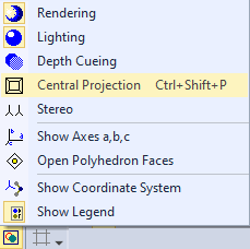
 button in the Display toolbar
and run the command Adjust Now from the menu or use the "hotkey" Alt+F9.
Adjusting can be combined with centering, which means the center of rotation is set into the center of all created atoms.
For that, push the
button in the Display toolbar
and run the command Adjust Now from the menu or use the "hotkey" Alt+F9.
Adjusting can be combined with centering, which means the center of rotation is set into the center of all created atoms.
For that, push the 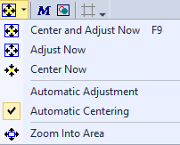
 button in the Move toolbar to activate the tracking mode.
The mouse cursor will change to this symbol:
button in the Move toolbar to activate the tracking mode.
The mouse cursor will change to this symbol: 

 button instead.
Press the left mouse button and keep it pressed while you move the mouse up and down, until you obtain a perspective impression according to your requirements.
To change the increment per mouse movement, use the same page of the Options dialog but change the value in the input field Viewing distance per cm mouse.
button instead.
Press the left mouse button and keep it pressed while you move the mouse up and down, until you obtain a perspective impression according to your requirements.
To change the increment per mouse movement, use the same page of the Options dialog but change the value in the input field Viewing distance per cm mouse. button in the Move toolbar.
(If this mode is active, the mouse cursor will change its shape.)
button in the Move toolbar.
(If this mode is active, the mouse cursor will change its shape.)