|
|
||||||
|
|
|
|
Download | |||
Diamond Version 5 User Manual: Display of structure pictureDrawing ellipsoidsThis article in brief:
Previous article: Designing bonds and contacts Overview
This article deals with the graphical representation of (anisotropic) displacement parameters, where atoms are displayed as ellipsoids instead of spheres only. This kind of representation leans of course heavily on the classical program ORTEP (Oak Ridge Thermal Ellipsoid Plot). The first part describes the styles, which are available for ellipsoid representation. "Displacement Parameters and Ellipsoid Representation" describes the relation between displacement parameters and their representation. You can exclude selected atoms or atom types from being displayed as ellipsoid. StylesWhen Diamond draws thermal ellipsoids, it tries to reproduce the style given for the drawn atom. A lot of ORTEP-like styles is available; see "Designing atoms" how to define the styles for atoms or atom types.
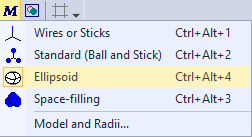
To simply switch between ellipsoid and non-ellipsoid representation, push the Models button (with the M symbol) in the Picture toolbar,
which opens the Models menu, and choose the Ellipsoid command.
The symbol of the Ellipsoid command is marked yellow, if the ellipsoid model is active for all atoms (if no atom is presently marked as selected in the picture) or active for the selected atoms.
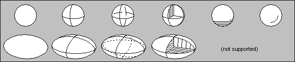
The following illustration shows the available styles, and how they are represented for a simple atom sphere or an ellipsoid:
From the left to the right: Solid/Empty, Cross 1, Cross 2, Octand, Shadow, Crescent
Thermal ellipsoids consist of the following parts:
a) the three semiaxes of the ellipsoid,
b) the border ellipse which is formed by the projection of the (threedimensional) ellipsoid onto the drawing area,
c) the three basic ellipses formed by each two of the three semiaxes of the ellipsoid. Each basic ellipse is divided into a front, visible and back, hidden part.
Diamond offers the following four styles to represent thermal ellipsoids:
1. Representation of only the border ellipse (corresponds to the ORTEP style with ORTEP instructions 704 and 714).
2. Representation of the border ellipse and the front parts of the basic ellipses (ORTEP: 702, 712).
3. Representation of the border ellipse and both front and back parts of the basic ellipses (ORTEP: 703, 713).
4. Representation of the border ellipse, the front parts of the basic ellipses, the semiaxes pointing towards you and an open, hatched octand (ORTEP: 701, 711).
The styles 2, 3, and 4 have direct pendants in the ‘normal’ ball-and-stick model. They correspond to the styles "Cross 1", "Cross 2", and "Octand" (compare illustration above). By combining style with interior, pattern, and edge color you may create empty, solid and even transparent ellipsoids. For the other styles (like "Shadow") only the border ellipse of the ellipsoid is drawn.
There are additional options for the ellipsoid representation, which you will find in the Atom Designs or Atom Group and Site Designs dialog.
To open the Ellipsoids dialog, choose the Thermal ellipsoids command from the Objects menu. Here you may select between the following additional options:
The ellipsoid probability factor (here given in percent) defines indirectly the size of the ellipsoids. The default value is 50 percent.
Atoms in ellipsoid representation may be edited individually like in ‘normal’ ball-and-stick representation. You can select an atom by clicking into the rectangle that surrounds the 2D projection of the ellipsoid.
The calculation of the border ellipse is the most time-consuming step when drawing a thermal ellipsoid. To speed up the drawing, you may activate the setting Draw border ellipses only in the dialog. But please do not forget to re-enable this setting when your picture is ready for output on printer or metafile. Note: Thermal ellipsoids will only be displayed, if valid anisotropic displacement parameters are given for at least one atom of the paramerer list. If no displacement parameters are given for an atom or if the atom is the corner of a coordination polyhedron, it cannot be represented as ellipsoid. But in general, a mixed representation of thermal ellipsoids and coordination polyhedra is possible. Displacement Parameters and Ellipsoid RepresentationDiamond works with isotropic as well as with anisotropic displacement parameters. To edit type and values of the displacement parameters, choose the Atomic parameters command from the Structure menu, which opens the Atomic Parameters dialog. Compare the article "Atomic parameters" for more information about atomic parameters.
You may define one isotropic and six anisotropic displacement parameters for each single atom of the parameter list. If anisotropic parameters are given, the field for the isotropic parameter may be valid, too (e.g. after importing data from a CIF file). In this case the isotropic parameter is the equivalent displacement parameter (e.g. Ueq).
Types of displacement parameters
Diamond works with isotropic displacement parameters of the types U and B as well as with anisotropic parameters of types U, B, and beta.
a) isotropic displacement parameters
Type B: exp (-B sin²(theta) / lambda²)
Type U: exp (-8 pi² U sin²(theta) / lambda²)
b) anisotropic displacement parameters
Type beta: exp ( -(h² beta11 + k² beta22 + l² beta33 + 2hk beta12 + 2hl beta13 + 2kl beta23) )
Type B: exp ( -0,25(B11 h² (a*)² + B22 k² (b*)² + B33 l² (c*)²
+ 2 B12 hk a* b* + 2 B13 hl a* c* + 2 B23 kl b* c*) )
Typ U: exp ( -2 pi² (U11 h² (a*)² + U22 k² (b*)² + U33 l² (c*)²
+ 2 U12 hk a* b* + 2 U13 hl a* c* + 2 U23 kl b* c*) )
Please note that Diamond does not calculate equivalent displacement parameters from anisotropic parameters, nor does it check the relation between anisotropic parameters and a given equivalent parameter. If for at least one atom isotropic and/or anisotropic displacement parameters are given, but no valid symbol (i.e. ? instead of U, B or beta), you will receive a warning message. When representing the thermal vibrations graphically, Diamond assumes type B which may lead to wrong results. In this case you should return to the Atomic Parameters dialog and correct the types for isotropic and/or anisotropic displacement parameters. Exclude Selected Atom Types From Ellipsoid Representation
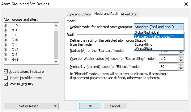
If anisotropic displacement parameters have not been defined for all atom types of the structure, it is often useful to exclude those atom types from being displayed as ellipsoids. In most cases, hydrogen atoms have not been refined anistropically, leading to hydrogen atoms in the structure picture, which are mostly rather big as compared with the other atom types that have been refined anisotropically. You can define that selected atom types shall be drawn as spheres instead of ellipsoids, like in the non-ellipsoid representation of the ball-and-stick model. To define a non-ellipsoid representation for one (or more) atom types, open the Atom Group and Site Designs dialog and switch to the Model and Radii page. Usually, the Default model for selected atom group(s) combobox will show Global/Individual for all atom groups, meaning that the atoms use the model that have been defined with the Model and Radii command/dialog for all atoms, e.g. ellipsoid model. Choose the atom type/group in the list Atom groups and sites, e.g. hydrogen, and change Default model for ... to Standard (Ball-and-stick).
The above shown dialog is described in more details in the article "Designing atoms". Rendering ellipsoid stylesDiamond version 2 still had the limitation that ORTEP-like styles (ellipses and open
octants) could only be displayed in flat mode but not in rendering mode,
where only solid ellipsoids were displayed instead.
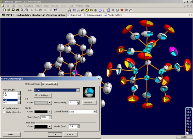
To define the hatching and color options for the octant walls, open the More Atom Style Settings dialog from the Style and Colors page of the Atom Design dialog or Atom Group and Site Designs dialog by clicking on the More Settings... button, which is only available, if a style with an octant representation is selected. Note that hatching of octant walls is supported in flat mode only, whereas in rendering mode the octant walls are painted with the color defined on the More Atom Style Settings dialog.
Previous article: Designing bonds and contacts
References: |
|
Page last modified October 09, 2023. Copyright © 2023 Crystal Impact GbR. All rights reserved. Contact Webmaster |