|
|
||||||
|
|
|
|
Download | |||
Diamond Version 5 User Manual: Display of structure pictureOrientation and Position
Previous article: Projection
This article informs you about the orientation and the position of the structure within the window or printout page, rsp. You will get to know:
- how to define the center of rotation,
- how to define the orientation and position of the structure,
- how to rotate and shift the structure with the mouse, the keyboard or by defining incremental values,
- how to define views along selected axes,
- how to define a view towards a plane given by Miller indexes h,k,l, - how to make use of the continuous rotation ("Rock and Roll").
Center of Rotation
By default, the center of rotation lies in the common origin of all three coordinate systems (crystal, reference, and view coordinate system), but can be changed manually or automatically. The center of rotation is an important reference point within the structure picture. By default, the center of rotation is projected into the center of the picture (or structure window), but can be shifted later.
Manual setting of the center of rotation
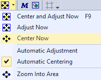
To set the center of rotation to the position of a selected atom, simply select the atom and then push the dropdown arrow right beneath
the
Or use the "hotkey" Shift+F9.
Instead of one single atom you can select multiple atoms and move the center of rotation into the center of the selected atoms.
If no atom has been selected, the center of rotation is moved into the center of all atoms.
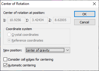
With the Center of Rotation dialog, you can also set the center of rotation into an arbitrary position (x,y,z) using either crystal or reference coordinates. To open this dialog, choose the Center of rotation command from the Display menu. There you can also decide if cell edges shall be considered, if the center of rotation is to be set into the center of all created atoms.
Automatic centering of the structure Check the checkbox Automatic centering in the Center of Rotation dialog, which is opened from the corresponding command in the Display menu, if you want the center of rotation be set automatically into the center of all created atoms after each building operation. That means, for example, that the center of rotation moves from the start-up value (0,0,0) to (1/2,1/2,1/2) in crystal coordinates after you have generated the contents of the unit cell, if this option is enabled. This centers the structure picture automatically within the structure window, since the center of rotation is automatically projected into the center of the structure window (unless the reference point has been shifted).
Note: The Automatic centering option is activated (on) by default.
Orientation and Position
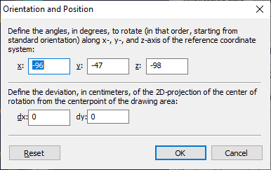
The current orientation of the structure is defined by the contents of the orientation matrix. The orientation matrix converts reference coordinates to view coordinates. In the basic orientation, where the orientation matrix is the identity matrix, the x-axis of the reference coordinate system points to the right, the y-axis to the top, and the z-axis towards the viewer.
The current orientation can be described with three rotational angles RX, RY, and RZ. If you start with the basic orientation, you first rotate RX degrees along the x-axis, then RY degrees along the y-axis, and finally RZ degrees along the z-axis to come to the current orientation. (Though there is an infinite number of angle triplets to rotate from the basic to the current orientation.)
The 3D coordinates of the objects cannot be shifted, but the 2D projection of the structure can be shifted horizontally and vertically. This 2D position of the projection of the structure in the 2D drawing area is relative to the center of the drawing area (center of the graphics pane as well as center of the printout page), and is given in centimeters.
Defining orientation and position To check or define the orientation or the position or both, choose the Orientation and Position command from the Display menu, which opens the Orientation and Position dialog. The current rotational angles in degrees are given in the input fields of the Define the angles ... group, whereas the position in centimeters relative to the center of the drawing area is given in the input fields of the Define the deviation ... of the 2D projection of the center of rotation ... group:
Resetting the orientation You can reset the orientation to the default orientation. By default, the default orientation is identical with the basic orientation, which means XR = YR = ZR = 0 for the three rotational angles. (The x-axis pointing to the right, y-axis up and z-axis pointing towards the viewer. In an orthorhombic, tetragonal, or cubic crystal system: a-axis to the right, b-axis up, and c-axis to the viewer.) The default orientation can be changed in the Viewing Direction dialog. See "Viewing Along Selected Axes" below how to set the default view axis.
Rotating and Shifting the Structure
You can rotate the structure with the mouse, step by step with the keyboard or incrementally by entering angle values.
Shifting of the structure within the drawing area is principally done in the same way.
Tracking modes
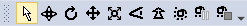
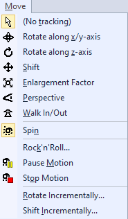
Diamond offers the so-called tracking mode for rotation as well as shifting. To enter the tracking mode, either push a button in the Move toolbar,
or use the corresponding command from the Move main menu:
The rotation or shifting will not be started before you press down the left mouse button.
With the left mouse button down, the structure rotates along selected axes or moves horizontally and vertically, until you release the left mouse button.
If you are rotating along x- and y-axis, vertical increments of mouse movement rotate along the x-axis of the view coordinate system,
horizontal increments along the y-axis.
When rotating along the z-axis, vertical increments of mouse movement rotate the structure along the z-axis.
When shifting the structure within the drawing area, the structure's position follows horizontal and vertical shifts of the mouse simultaneously.
You can alter the speed of rotation, that means the amount of rotation relative to mouse movement, as well as the ratio of mouse shift and structure shift on the Tracking page of the Options dialog.
To open the Options dialog, choose the Options command from the Tools menu.
The current values, which are global for all structure windows, are defined on the Tracking page
in the input fields Degrees along ...axes per cm mouse movement and Shifting in cm per cm mouse movement, rsp.
By default, the mouse cursor changes to the same symbol that is displayed when entering the tracking mode but without arrow, indicating that you cannot select any menu command or push any toolbar button while you are rotating or shifting the structure.
You can hide the mouse cursor during rotation or shifting, rsp. For that, check the checkbox Hide mouse cursor while tracking on the Tracking page of the Options dialog.
Thus the cursor cannot reach the window's borders so that you may rotate or shift the structure nearly continuously.
Otherwise you cannot continue rotation or shifting, when the mouse cursor has reached the border of the Windows screen,
unless you release the left mouse button, move the mouse back to the screen's center and re-enter rotation or shifting mode, rsp.
Stepping
While tracking means simultaneous movement of structure and mouse, stepping stands for stepwise movement of the structure caused by hits on several keys.
Each hit on the Cursor up and Cursor down key rotates along the x-axis, whereas each hit on the Cursor left and Cursor right key rotates along the y-axis.
To rotate along the z-axis, use the Page up and Page down keys.
To shift the structure within the drawing area, hit the cursor keys on the numerous pad.
To change the amounts of rotation or shift for each single keystroke, use the Stepping page of the Options dialog.
To open the Options dialog, choose the Options command from the Tools menu.
Define the amount of rotation (in degrees) along the x-, y- and z-axis for each single hit on a cursor or PageUp/PageDown key
in the input fields X, Y and Z of the input field Degrees along ...axes per keystroke.
Define the amount of horizontal and vertical shift for each hit on a cursor key (numerous pad) in the input fields Horizontal and Vertical of the group Shifting in cm per keystroke. Spin option to accelerate motion The Spin option is either available as command in the Move menu or as a button in the Move toolbar.
Using this command/option you can let the model rotate continuously around one or more axes. For example, you can "push" the model into rotation using your mouse: Once the "Spin mode" has been activated, and a tracking mode (e.g. "Rotate along x/y-axis") has been activated, simply move the mouse into the structure picture, press the left mouse button and keep it pressed while you rapidly move the mouse in some direction. Finally, release the mouse button. The model in the structure picture will start rotating continuously according to the direction in which you moved the mouse. You can change the rotation simply by repeating the "mouse pushing" procedure described above. The closer the mouse pointer to the rotation center, the slower will be the rotation, and vice versa. If you would like to stop the rotation, simple select the Pause motion or Stop motion command from the Move menu, or press the corresponding button in the toolbar. Afterwards, you should also disable the "Spin" mode (running the Spin command again) in order to prevent yourself from surprising results during tracking operations later on.
Defining incremental values
To rotate the structure for an arbitrary amounts of degrees along selected axes, choose the Rotate Incrementally command from the Move menu,
which opens the Rotate Structure Picture dialog, where you can define the amounts of rotation in degrees for each axis.
You can simply repeat the incremental rotation by pushing the Apply button for each increment. To shift the structure for arbitrary centimeters within the drawing area, choose the Shift Incrementally command from the Move menu, which opens the Shift Structure Picture dialog, where you can enter the horizontal and vertical amounts of shift in centimeters.
Viewing Along Selected Axes
To define a view along the a, b, or c axis of the unit cell, or along the x, y, or z axis of the reference coordinate system, or along an arbitrary direction,
choose the Viewing Direction command from the Display toolbar, which opens the Viewing Direction dialog.
Viewing along an axis
When pushing one of the six pushbuttons a, b, c, x, y or z,
the structure will be oriented in this way that the vector a, b or c of the unit cell or the x-, y- or z-axis rsp.
of the reference coordinate system points towards you.
If the checkbox Opposite direction is checked, the selected axis points away from you instead towards you.
Viewing along a vector defined by uvw
Enter the u, v, and w value into the input fields u, v and w to define a vector pointing from the origin to the point with crystal coordinates (u, v, w). The structure will be oriented according to the currently set uvw values, if the Set button is pushed.
Defining axis
To define a view axis through two selected atoms, push the Define axis button.
This closes the Viewing Direction dialog and lets you select two atoms #1 and #2.
An axis is defined between these two atoms. The center of rotation will be set into atom #1.
The structure will then be oriented in this way that the axis to atom #2 points towards you.
Defining a view as standard orientation You can define a preferred view as default orientation for new structures or as standard orientation, when the Reset button in the above mentioned Orientation and Position dialog is pushed. For that, check the checkbox Save view as standard orientation in the Viewing Direction dialog. If for example the button a is pushed and then this dialog closed, all new structures have the a-axis pointing towards you as default orientation. The Reset button will let the a-axis point towards you, too.
Viewing Towards a Plane Given By Miller Indexes h,k,l
You can choose an orientation where a plane with Miller indexes h, k, and l is projected to the xy-plane of the view coordinate system,
that means the plane is parallel with the drawing or printing area.
You can enter values for h, k, and l in the View towards plane group of the Viewing Direction dialog.
You may use integer numbers as well as non-integer numbers. The Miller indexes corresponding to the current orientation are given below the three input fields. When calculating the Miller indexes from the current orientation, Diamond tries to get the nearest integer values for h, k, and l unless no integer value less than 100 can be found for h, k, and l.
Continuous Rotation ("Rock and Roll")
Diamond offers a mode with continuous rotation of the structure along selected axes with arbitrary rotational amounts, which is called "Rock and Roll". ("Rock" because you can also define border values, where the rotational direction is inverted, that means, the structure turns back and forth.)
Switching Rock and Roll on and off
To switch Rock and Roll on or off, using the default settings for rotational amounts and selected axes, use the Rock'n'Roll command in the Move main menu.
Changing the settings To select the axes for rolling, select an axis for rocking (or no axis for no rocking), and to specify the rotational speeds, choose the Rock'n'Roll command from the Move menu, which opens the Rock'n'Roll dialog. Define the rotational speeds referring to the three axes x, y, and z of the view coordinate system in degrees per second in the group Speed of rotation (input fields x-axis, y-axis, z-axis). If multiple axes are selected (that means the corresponding angle in the input field is not zero), the rank order of axes during rotation is x, y, z. If the rotation should change its direction for a selected axis, check the appropriate radio button in the Rocking around axes group, or choose No rocking. The border angles in degrees for rocking can be entered in the two input fields of the group Border angles. If the continuous rotation reaches one of these angle values, the direction of the rotation referring to the axis selected in Rocking around axes is inversed.
Previous article: Projection |
|
Page last modified August 20, 2022. Copyright © 2022 Crystal Impact GbR. All rights reserved. Contact Webmaster |
 button in the Picture toolbar and then choose the command Center Now from the popup menu: