|
|
||||||
|
|
|
|
Download | |||
Diamond Version 5 User Manual: Building up structural partsFilling Cell Ranges
For crystal structures without molecular subunits or structures where molecules do not play a major role, the probable easiest way to get an overview of the crystal structure is to generate atoms within a range of the lattice. This range may have the shape of a (rectangular) parallelepiped or of a sphere. Here in Diamond, we calls this generation of atoms within a given range, shortly "Filling", e.g. filling the unit cell.
Unit cell
Super cell
Cell range
Filling a box or sphere around a central atom
Filling a Rectangular or Circular Area of the Screen
Previous article: Adding some or all atoms (and bonds) directly Filling the Unit Cell
Filling the unit cell means the generation of all atoms with crystal coordinates
with -epsilon <= X <= 1 + epsilon and -epsilon <= Y <= 1 + epsilon and -epsilon <= Z <= 1 + epsilon.
The epsilon value prevents atoms which are (nearly exactly) on edges or faces of the unit cell from being excluded during the filling procedure.
If epsilon is e.g. 0.01, the real cell range to be filled has XMIN=YMIN=ZMIN= -0,01 and XMAX=YMAX=ZMAX= 1,01 in crystal coordinates.
To fill the unit cell, choose the Unit Cell command from the Fill submenu of the Build menu.
Alternatively, you can use the (red marked) button
The filling of the unit cell is affected by the filter, which is described in details in the article "Filter".
By default, this function also generates the edges of the unit cell automatically. If you do not want cell edges to be created automatically when filling the unit cell, do the following steps:
1. From the Build menu,
open the Fill submenu and choose the Super Cell command.
2. In the Fill Super Cell dialog,
switch off the checkbox Generate cell edges automatically.
3. Choose the option Unit cell from Select super cell.
4. Close the dialog with OK.
Diamond will save the setting Generate cell edges automatically in its Windows registry section. That means, in all subsequent calls to a function that fills the unit cell or a super cell, no cell edges will be created automatically. To re-enable the automatic generation of cell edges, repeat the above step, but switch on the Generate cell edges automatically checkbox.
Use the Fill super cell dialog, too, if you want to change the epsilon value.
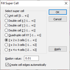
Filling a Super Cell
The usage of a so-called "super cell" instead of the unit cell only, is an alternative way to get insight into a bigger part of the crystal structure, especially if the unit cell dimensions are rather small. A super cell is defined as an integer multiple of the unit cell.
To fill the contents of a super cell, choose the Super Cell command from the Fill submenu of the Build menu. This opens the Fill Super Cell dialog.
The following types of super cells (including the rather simple unit cell itself) are available.
(XMIN, YMIN, ZMIN, XMAX, YMAX, and ZMAX define the borders of the super cell in crystal coordinates.)
To prevent atoms which are (nearly exactly) on edges or faces of the unit or super cell from being excluded during the filling procedure, an epsilon value is defined in the Epsilon input field in the Fill super cell dialog. This value will be subtracted from the XMIN, YMIN, and ZMIN values, and added to the XMAX, YMAX, and ZMAX values. If e.g. a super cell consisting of 3 x 3 x 3 = 27 cells is to be filled, the real dimensions are XMIN = YMIN = ZMIN = -1.01 and XMAX = YMAX = ZMAX = 2.01, if the default value of 0.01 for epsilon is used.
The filling of the unit cell is affected by the filter, which is described in details in the article "Filter".
By default, this function also generates the edges of the unit cell or all edges of and within the super cell automatically. If you do not want cell edges to be created automatically during this operation, switch off the Generate cell edges automatically checkbox.
Diamond will save the setting Generate cell edges automatically in its Windows registry section. That means, in all subsequent calls to a function that fills the unit cell or a super cell, no cell edges will be created automatically. To re-enable the automatic generation of cell edges, you must switch on the Generate cell edges automatically checkbox.
You can either make use of the OK button to fill the selected super cell, or use the Apply Now button, which does not close the dialog as OK does.
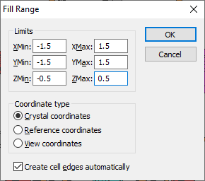
Filling a Cell Range
While the previously described functions (filling the unit cell or a super cell), work with the unit cell or integer multiples of the unit cell only, you may define a parallelepiped by six distinct border values XMIN, YMIN, ZMIN, XMAX, YMAX, and ZMAX.
These border values refer to one of three possible coordinate systems used in Diamond:
To fill a cell range, choose the Range command from the Fill submenu of the Build menu. This opens the Fill Range dialog:
The filling of the cell range is affected by the filter, which is described in details in the article "Filter".
By default, this function also generates the edges within the given cell range automatically.
If you do not want cell edges to be created automatically during this operation, switch off the Create cell edges automatically checkbox. Diamond will save the setting Create cell edges automatically in its Windows registry section. That means, in all subsequent calls to a function that fills a cell range, no cell edges will be created automatically. To re-enable the automatic generation of cell edges, you must switch on the Create cell edges automatically checkbox. Filling Boxes or Spheres Around Selected Atoms
If you want to fill a cell range but do not know suitable border values, you should make use of one of the following methods:
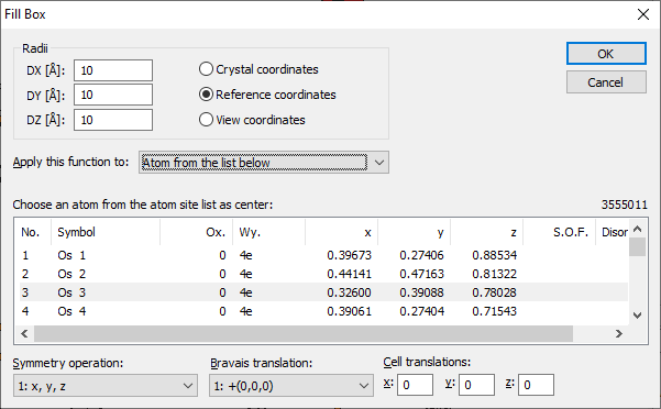
Filling a box around a selected atom
This fills a parallelepiped with border values referring to the crystal coordinate system or a rectangular parallelepiped referring to the reference or view coordinate system. The center is defined by the position of an atom, which has been selected from the parameter list. Such a parallelepiped is often called an enclosure box or simply a box.
To fill a box, choose the Box command from the Fill submenu of the Build menu. This opens the Fill Box dialog:
The radii of the box are defined by the three values given in DX, DY, and DZ. Their dimensions depend on the selected coordinate system:
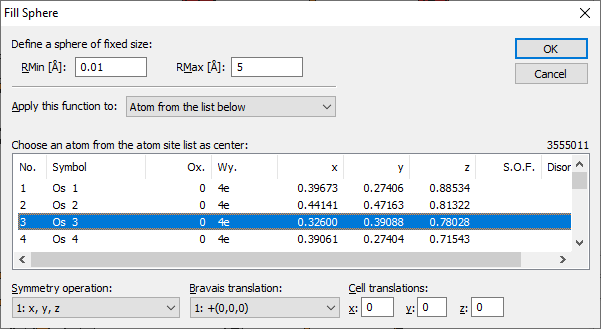
Filling a sphere around a selected atom
This fills a sphere around a center, which is defined by an atom of the parameter list. Such a sphere is often called enclosure sphere.
To fill a sphere, choose the Sphere command from the Fill submenu of the Build menu. This opens the Fill Sphere dialog:
The size of the enclosure sphere is limited by the two boundary values RMin and RMax in Angstroems.
Selection of the central atom
The central atom (of the sphere or box, rsp.) can be selected from the atomic parameter list and - as far as necessary - from the list of symmetry operations, Bravais translations and integer cell translations, if necessary. Applying the command to all atoms of the parameter list The dropdown box Apply this function to allows you to apply the filling of a box or sphere, rsp., not only to a single atom site of the parameter list but also to multiple atom sites. Here, you define which atom(s) shall be considered as the center(s) of the sphere(s) to be filled. You can either use atoms you have selected before executing the "Fill Box" (or "Fill Sphere") command ("selected atoms"), "all atoms in the structure picture", or special "atom from the list below" in which case you can precisely define the center atom based on the parameter list, the symmetry operation, the Bravais translation and the cell translations.
Filter
Filling a Rectangular or Circular Area of the Screen
Both previously described functions (filling of a cell range or filling a box) may work with rectangular parallelepipeds with border values referring to the view coordinate system.
But in most cases the border values in view coordinates are difficult to obtain, and thus an interactive method of filling an area is to be preferred.
You define the X and Y coordinates of the parallelepiped by spreading a rectangular area on the screen (in the structure window).
The border values in z-direction must then be given numerically.
Before you perform the filling of the rectangular area, the projection must be set to parallel. To ensure parallel projection, do the following:
1. From the Display menu, choose the Picture Settings command.
2. On the Projection page of the Picture Settings dialog, check the parallel checkbox in the Projection group, if it has not yet been checked.
3. Close the dialog with OK. To fill a rectangular area on the screen, choose the Rectangular Area command in the Fill submenu of the Build menu.
(The mouse cursor changes to a special symbol
To fill the contents of a rectangular area, do the following steps:
1. Move the mouse cursor to the upper left corner of the desired position of the rectangular area.
2. Press down the left mouse button, and (with mouse button down) move the mouse cursor to the lower right corner of the area.
3. Release the left mouse button, when you have reached the desired position.
4. In the Fill cell range dialog, define ZMin and ZMax (you may also alter the values for XMin, YMin, XMax, and YMax, if necessary), then press OK. The calculation of the values XMin, YMin, XMax, and YMax considers the current orientation as well as the current position of the structure picture in the structure window and the current enlargement factor. The z values refer to the origin of the unit cell, that means (0,0,0) in both crystal and reference coordinates. See the chapters "Orientation and Position" and "Projection" about orientation of the structure, projection and enlargement factor. Filling a circular rather than a rectangular area
As an alternative to the above described rectangular area, the command Circular Area (from the same Fill submenu of the Build menu)
fills a cylinder with its caps parallel to the
screen with atoms. Once it has been activated, the mouse cursor changes to a different special symbol
Filter Both the filling of the rectangular and the circular area are affected by the filter, which is described in details in the article "Filter".
Previous article: Adding some or all atoms (and bonds) directly |
|
Page last modified June 06, 2023. Copyright © 2023 Crystal Impact GbR. All rights reserved. Contact Webmaster |
 from the Build toolbar or the acceleration key Shift+Ctrl+U.