|
|
||||||
|
|
|
|
Download | |||
Diamond Version 5 User Manual: Display of structure picturePlane and line objects
This article describes how planes can be defined by hkl or as (best) plane through a set of three or more atoms or a line through two or more atoms.
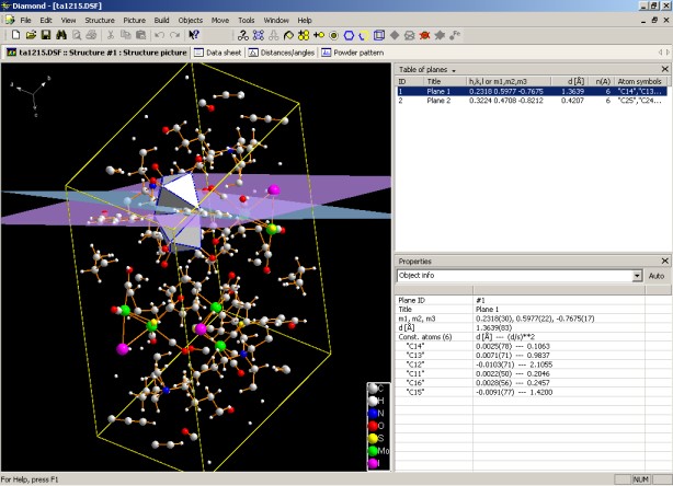
Previous article: Coordinate system OverviewPlane objects can be defined, either by h,k,l and a distance from origin, given as n*d, or through a set of three or more points (atoms). (Least-squares) line objects can be defined in a similar way. Please note that plane and line objects will be displayed in rendering mode only but not in flat mode. The screenshot below - made with version 3, where plane and line objects were introduced - shows two least-squares planes, in different colors and with transparency, in the structure picture pane. In the top right pane, you find a table of plane objects and in the properties pane below details about the selected plane, especially the distances of the constituent atoms from the plane and their standard uncertainties.
These plane and line objects can be used for display or for geometric research, or both. Diamond offers the calculation of angles between planes or lines as well as between a plane's normal and a line. Additionally you can calculate the distances of atoms from a plane or line. All results are given with standard uncertainties, if uncertainties are given with the structure data. This is described in more detail in the article "Extended geometric infos: Angles between planes etc.".
Creating plane and line objectsThe commands to create, edit or delete planes are available in the Planes sub-menu of the Objects menu.
Define a lattice plane by h, k, l, and distance from origin The Create Lattice Plane command opens the Add Lattice Plane dialog where you can create a plane object in the structure picture based on the corresponding Miller indices h,k,l. The Orientation & Position page is part of the "Add Lattice Plane" dialog (and of the "Edit Plane" dialog, which is described later). Here, the parameters describing a plane can be defined: The orientation of the plane is given by the Miller indices h, k and l; the position perpendicular to this direction is given as the distance from the origin of the crystal coordinate system in d(hkl) units. These units are actually integer values but you may define floating point values as well. When you are about to add lattice planes, you may define multiple values and/or even integer ranges in the input field distance from the origin. For instance, "1-3;5" creates a series of four parallel planes, 1*d, 2*d, 3*d, and 5*d Angstroems apart from the origin. The Style page is the second part of the "Plane Through Atoms" dialog (and also of the "Line Through Atoms" dialog as well as the "Edit Plane" dialog and "Edit Line Style" dialog). Here, you can define the style (e.g. color) of the plane or line, rsp., to be created or an already existing plane or line, rsp. Title: You can assign a title/name to the plane or line so that you can identify it later on more easily e.g. in the "Table of planes/lines" or when you calculate distances and angles. Display this plane/line in structure picture: Here you can select if you
would like to use the current plane/line for measurements only, or if you would
also like to display it in the structure picture. Color: Here you can select the color of the currently selected plane(s) or line(s) (or the plane/line to be created). Transparency: Planes or lines can be displayed either opaque (non-transparent) or also transparent. A transparency value of 0.0 is equivalent to opaque, while a value of 1.0 corresponds to fully transparent. Normally, you should use a value in between (e.g. the default value of 0.5).
Creating a plane through selected atoms The Create Plane Through Atoms command - in contrast to the above mentioned command - creates a plane through the currently selected atoms. It is only accessible if at least three atoms are selected in the structure picture. It opens the Plane Through Atoms dialog where you can create a least-squares plane through the atoms you have selected. The plane parameters will be calculated as the minimum of the square of the sum of the distances between the selected atoms and the plane. The Position page is part of the "Plane Through Atoms" dialog. All atoms you have selected before calling the "Objects/Planes/Create Plane Through Atoms..." command are displayed in the "Constituent atoms" list, along with their distances to the current plane (d [Å]) and the corresponding standard deviations (s [Å]). You can mark the checkboxes of the atoms which shall actually be taken into account in the calculation of the least-squares plane. The plane parameters will be calculated as to minimize the sum of the squares of the distances between marked atoms ("Constituent atoms") and the plane. The parameters of the plane are given below the list of Constituent atoms. Please note that a plane defined through three or more atoms cannot be changed in position and orientation thereafter, just style options can be altered using the command "Objects/Planes/Edit Plane", see below.
Creating a line object through selected atoms The commands to create, edit, or delete a line object are available from the Lines sub-menu of the Objects menu. The Create Line Through Atoms command is only accessible if at least two atoms are selected in the structure picture. It opens the Line Through Atoms dialog where you can create a least-squares line through the atoms you have selected. The line parameters will be calculated as the minimum of the square of the sum of the distances between the selected atoms and the line. On the Position page of the "Line Through Atoms" dialog, all atoms you have selected before calling the "Create Line Through Atoms..." command are displayed in the "Constituent atoms" list, along with their distances to the current line (d [Å]) and the corresponding standard deviations (s [Å]). You can mark the checkboxes of the atoms which shall actually be taken into account in the calculation of the least-squares line. The line parameters will be calculated as to minimize the sum of the squares of the distances between marked atoms ("Constituent atoms") and the line. The parameters of the line are given below the list of Constituent atoms.] The style of the line is defined on the Style page of the dialog. Define the color and transparency as is described above for planes. Line style defines, if the line object comes as a straight line ("solid") or is stippled ("dashed" or "dotted"). Weight defines the width of the line in a structure picture in millimeters (mm). A width of zero mm results in a line that is only 1 pixel wide.
Tables and properties of plane and line objectsThe data pane in the right part of the typical Diamond structure picture window may contain tables of several kinds of objects and other informations, see the articles "Data Pane: Data sheet, tables, properties view, and atom list" and "Tables of objects like atoms, bonds, molecules etc.". Here we have a closer look at two tables, one for the plane objects and one for the line objects. The Properties view, by default located below the tables shows detailed information about the plane or line object, rsp., currently selected in the table. For every plane, its ID number, its title, and the visibility flag (yes or no) is given. For an hkl plane, the hkl-values and the distance in Angstroem from origin (d) is given, for a L.S. plane, the plane parameters as well as the contributing atoms are displayed. For every line, the line ID, its title, its visibility as well as the line parameters and the contributing atoms are displayed. Note: The columns to be shown as well as some additional settings like grid etc. can be defined in the Data Table Settings dialog, which is available e.g. by the command View -> Table -> Table Settings. The Properties view shows all informations, independent, if one or more columns have been hidden using the above mentioned table settings dialog. While the column for the constituent atoms lists the atom symbols only, the properties view shows a list of all constituent atoms with label, distance from table (or line, rsp.), in Angstroem and the standard uncertainty of the distance value. Checking the planarity or linearityThere are several ways to get the planarity of a least-square plane through atoms or the linearity of a least-squares line: Create Plane/Line Through Atoms dialogs When you have selected the atoms where you want to create a L.S. plane or LS.line, rsp,, from, you can check the table of atoms in the Create Plane Through Atoms or Create Line Through Atoms dialog, rsp. You can clear or re-set checkmarks in the list to view how the planarity/linearity changes, if you omit one or more of the selected atoms. Using the table of plane objects/line objects and "Object info" in the "Properties" view When you show the table of plane objects or line objects, the default ("automatic") setting of the Properties view shows details about the plane/line selected in the table as "Object info". The list of constituent atoms is at the bottom with d values and (d/s)2. Planarity and linearity property without defining a plane or line object You need not define a plane or line object to check the planarity or linearity of atoms in the structure picture. Simply select at least three atoms and check the planarity directly in the Properties view. This is the easiest way, if you neither need to display a plane object nor need a plane object for geometric calculations. Choose the Planarity option from the drop-down box at the top of the Properties view. This lists all selected atoms and their distances with standard uncertainties from a temporary L.S. plane. Choose the Linearity option instead to check the linearity of the selected atoms and their distances from a temporary L.S. line. Editing or destroying plane or line objectsEditing or destroying plane or line objects is available through the Objects main menu and from the table of plane objects and line objects, rsp. The Edit Plane command opens the "Edit Plane" dialog for the plane object that is currently selected in the "Table of planes". The Edit Line command opens the "Edit Line Style" dialog from the "Table of lines". Even two or more planes or lines, rsp., can be edited at one time (provided that multiple rows in the table have been marked as selected). Please note that when you are editing one or even more (already existing) lattice planes, you cannot enter multiple values or ranges in the Distance from origin field. The Delete Plane/Line commands are available, if at least one plane or line, rsp., is selected in the table. All selected planes or lines, rsp., will be deleted. Additionally editing or deleting (L.S.) planes or lines through atoms is possible directly from the constituent atoms. If at least one of the constituent atoms of a L.S. plane or line, rsp., is selected, you can use the context menu of this atom to either edit the associated plane or line, rsp., or delete it. The Edit -> Plane Through Atoms command of the context menu opens the "Edit Plane" dialog for the plane object that is indirectly selected by at least one of its constituent atoms. The Edit -> Line Through Atoms command opens the "Edit Line Style" dialog for the line object that is indirectly selected by at least one of its constituent atoms. Even two or more planes or lines, rsp., can be edited at one time (provided that multiple atoms belonging to multiple planes or lines, rsp., are selected in the structure picture). The equivalent commands from the Destroy sub-menu of the selected atom's context menu deletes the plane (or line, rsp.) where the selected atom is constituent atom of.
Previous article: Coordinate system
References: |
|
Page last modified September 02, 2023. Copyright © 2023 Crystal Impact GbR. All rights reserved. Contact Webmaster |